16. Cluster rendering (WireGL)
VEGA ZZ includes the support for cluster rendering provided by the WireGL library developed at Stanford Computer Graphics Lab. VEGA ZZ recognizes WireGL maximizing the rendering performance for this library.
WARNING:
The files required for this feature were removed from 3.1.2 setup, but are available on request.
16.1 How WireGL works (from the original manual)
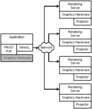
WireGL is implemented using the standard client/server network model. The client acts as a graphics source, generating graphics commands to be rendered on the cluster. The server machines act as graphics sinks, receiving graphics commands from the network and rendering them. Below is a diagram of the WireGL system.
The WireGL client (on the left) runs the host application. The client works by replacing the system opengl32.dll or libgl.so with its own library which exports the same OpenGL interface. The application therefore does not need to be modified in any way to work with the WireGL client driver. When the application loads, it will dynamically link with the WireGL client driver which will connect and begin transmitting graphics commands to the rendering servers.
The WireGL servers are responsible for rendering the graphics commands on the client's behalf. Each rendering server is connected to an output device, typically a projector, which are arranged to create a tiled display. The server is configured to only output its portion of the display.
16.2 Configuration of the rendering servers
The configuration of the rendering server is very easy: you must make a copy of the WireGL Server directory (see the VEGA installation folder) to each workstation performing the distributed rendering. Two are the ways to run the software:
Manual run: double click the StartServer.bat batch file. This is useful to test WireGL without the service installation.
Service run: double click the Service_Install.bat batch file to install the rendering context as service. The rendering context will be started in background and the manual activation is not required at every system restart. To remove the service, double click the Service_Uninstall.bat batch file.
Here are reported the pipeserver command line options. There are useful if you want use configurations not supported by the batch files.
-p portnum
Specifies the port number to respond to client requests.
-f
Specifies full screen mode. Opens an undecorated full screen window for
rendering.
-h
Displays command line option help.
-nogfx
Disregard all graphics commands.
-sync
Make the X connection synchronous. (Non-Windows only.)
-install
Install the pipeserver as a Windows service. (Windows only.)
-remove
Remove the pipeserver from the Windows service registry. (Windows only.)
16.3 Client configuration
OpenGL Setup
utility allows to install the WireGL rendering library: you must select WireGL
and click Apply button. During the installation the wiregl.conf
file is created in VEGA ZZ installation directory, containing the default
parameter for the local rendering at 800x600 resolution trough the TCP/IP
network. To test WireGL on the local machine, you must start the rendering
server (run StartServer.bat in the WireGL Server directory) and
VEGA ZZ: if it's all right, the OpenGL output will be redirected to a separated
800x600 window.
The wiregl.conf file must be changed to inform the WireGL client about the
servers (pipeservers) that will be used for the tile rendering.
The following documentation is extracted from the original manual and it's
copyrighted by the WireGL Authors.
The wiregl.conf file defines the layout and locations for the pipeservers the WireGL client is to use for rendering. This file is parsed when the context is created, typically at application startup. Below is an example of a simple config file for two rendering servers:
# Setup Machine1
pipe tcpip://machine1.stanford.edu
pipe_extent 0 0 1024 768

# Setup Machine2
pipe gm://machine2
pipe_extent 1024 0 1024 768
Each pipeserver is defined starting with the pipe command which indicates the connection information. In the above example, the connection to machine1 is made using TCP/IP, while machine2 uses Myrinet's GM. The pipe_extent line specifies which part of the output display the server is responsible for rendering. In this case, machine1 will render the left 1024x768 and machine2 renders the right 1024x768.
Here is the list of configuration commands:
pipe conntype://machinename:port
Begins a pipeserver definition. conntype can be tcpip for a TCP/IP
connection or gm for a Myrinet GM connection. machinename is the
name which should be used for making the connection on the specified connection
type. The port (optional) indicates which TCP/IP port the machine should
use to make the connection (default 7000).
pipe_extent x_start y_start width height
Determines what portion of the pipeserver is responsible for entire output. The
coordinates (x_start, y_start) establish the offset from the lower
left corner of the tiled display. (width, height) determine the
size of the rendering window. Default (0 0 1024 768).
pipe_window x y
Determines the upper left corner position of the rendering window on the server
desktop.
feather_top size cp1 cp2 cp3 cp4
feather_bottom size cp1 cp2 cp3 cp4
feather_left size cp1 cp2 cp3 cp4
feather_right size cp1 cp2 cp3 cp4
Controls the feathering for overlaping tiles. size is the number of
pixels to apply the feathering. (cp1, cp2, cp3, cp4) are the control
points for a cubic spline used for evaluating the alpha values.
sync_on_swap z
If z is "1", the client waits until each pipeserver is done rendering
before allowing the the swap command to return to the application. If
"0", then client can issue commands as fast as the network will allow.
Default: 0.
sync_on_finish z
If z is "1", the client waits until each pipeserver is done rendering
before returning from glFinish call to the application. If "0",
glFinish will flush any network pipes but return before actual rendering is
complete. Default: 0.
draw_bbox z
If z is "1", the client draws bounding boxes used for geometry
bucketing. Default: 0.
bucket_size n
Sets the number of bytes of client side buffering before geometry bucketing is
performed. This can be increased/decreased to improve bucketing preformance.
Default: 8192.
beginend_max n
Sets the maximum number of glBegin/glEnd blocks between geometry bucketing
operations. This can be set to improve bucketing preformance. Default: 2^32.
broadcast z
If z is "1", geometry bucketing is disabled. All primatives will be
sent to each pipeserver. Default 0.
depth_bits n
Specifies the default depth bits used in rendering. Default: 24.
stencil_bits n
Specifies the default stecil bits used in rendering. Default: 8.
use_ring z
If z is "1", configures WireGL into "ring mode" where
servers are connected in using a ring topology instead of direct connections to
the client. Can improve performance in some serial applications. Default: 0.
Examples:
# 2x1 configuration
# TCP/IP network

# Resolution:
# Each display: 1024x768
# Each server:  1024x768
# Total:        2048x768

# Setup Machine1
# Left
pipe tcpip://machine1.farma.unimi.it
pipe_extent 0 0 1024 768
# Setup Machine2
# Right
pipe tcpip://machine2.farma.unimi.it
pipe_extent 1024 0 1024 768
# 3x3 configuration (virtual)
# 3 displays for each server thanks to the Matrox
# extended desktop (Parhelia or P750 cards required)
# TCP/IP network

# Resolution:
# Each display: 1024x768
# Each server:  3072x768
# Total:        3072x2304

# Setup Machine1
# Top (first row)
pipe tcpip://machine1.farma.unimi.it
pipe_extent 0 0 3072 768
# Setup Machine2
# Center (second row)
pipe tcpip://machine2.farma.unimi.it
pipe_extent 0 768 3072 768
# Setup Machine3
# Center (third row)
pipe tcpip://machine3.farma.unimi.it
pipe_extent 0 1536 3072 768
# 3x2 configuration
# 30 pixel overlap between projectors
# Using a linear alpha ramp for feathering
# TCP/IP network

# Resolution:
# Each display: 1024x768
# Each server:  1024x768
# Total:        3012x1506 (including overlapping)

# Turn on swap syncing
sync_on_swap 1

# Setup Machine1
# Lower left
pipe tcpip://machine1.stanford.edu
pipe_extent 0 0 1024 768
feather_top 30 1.0 0.666 0.333 0.0
feather_right 30 1.0 0.666 0.333 0.0

# Setup Machine2
# Lower middle
# Note: 1024-30=994
pipe tcpip://machine2.stanford.edu
pipe_extent 994 0 1024 768
feather_top 30 1.0 0.666 0.333 0.0
feather_right 30 1.0 0.666 0.333 0.0
feather_left 30 1.0 0.666 0.333 0.0

# Setup Machine3
# Lower right
# Note: 1024-30+1024-30=1988
pipe tcpip://machine3.stanford.edu
pipe_extent 1988 0 1024 768
feather_top 30 1.0 0.666 0.333 0.0
feather_left 30 1.0 0.666 0.333 0.0

# Setup Machine4
# Upper left
# Note: 768-30=738
pipe tcpip://machine4.stanford.edu
pipe_extent 0 738 1024 768
feather_bottom 30 1.0 0.666 0.333 0.0
feather_right 30 1.0 0.666 0.333 0.0

# Setup Machine5
# Upper middle
pipe tcpip://machine5.stanford.edu
pipe_extent 994 738 1024 768
feather_bottom 30 1.0 0.666 0.333 0.0
feather_right 30 1.0 0.666 0.333 0.0
feather_left 30 1.0 0.666 0.333 0.0

# Setup Machine6
# Upper right
pipe tcpip://machine6.stanford.edu
pipe_extent 1988 738 1024 768
feather_bottom 30 1.0 0.666 0.333 0.0
feather_left 30 1.0 0.666 0.333 0.0